What Is the Difference Between a Bushing and an Adapter
Bushings and adapters are similar plumbing fittings but have key differences in design, threading, and usage.
Read More
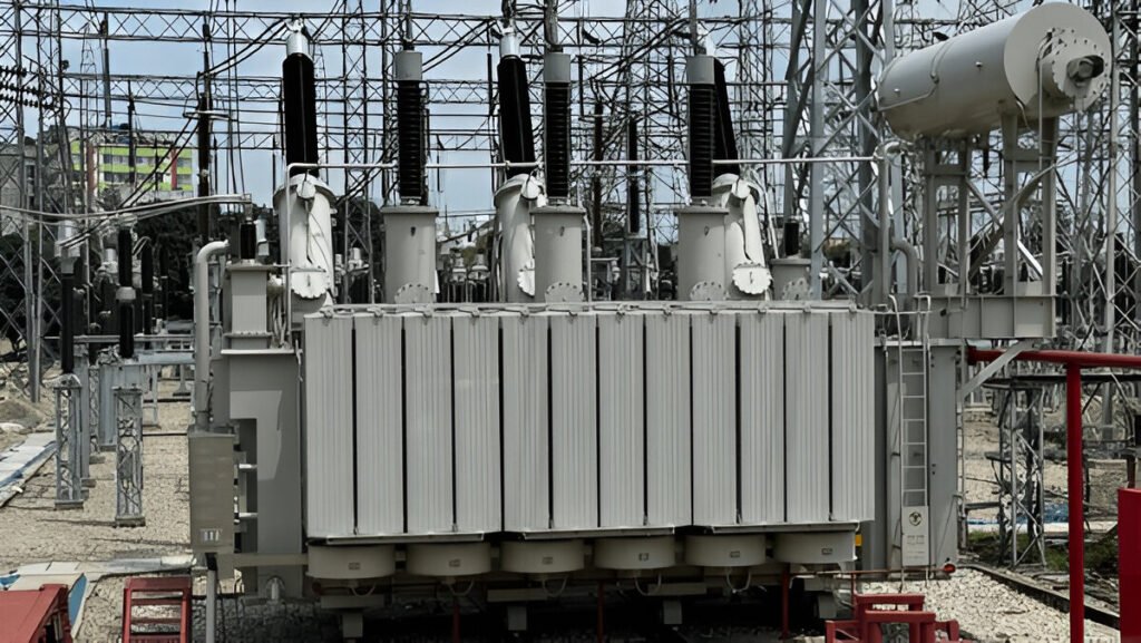
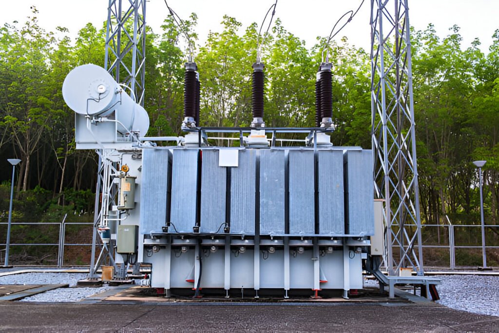
Transformers are a vital component in the transmission and distribution of electrical power. These devices enable the efficient transfer of electricity by converting voltage levels between circuits, allowing power to be transmitted over long distances with minimal losses.
The operating principles of transformers revolve around the interaction of magnetic fields and alternating currents. In this blog post, we will delve into the inner workings of transformers and explore their fundamental principles of operation.

A transformer is an electrical device that transfers electrical energy between two or more circuits through electromagnetic induction. It consists of two or more coils of wire, known as the primary winding and secondary winding, wrapped around a core made of a magnetic material, such as iron or ferrite. The primary winding is connected to the input voltage source, while the secondary winding delivers the transformed voltage to the load.
Transformers play a vital role in the transmission and distribution of electrical power. They are used to step up or step down the voltage levels, allowing for efficient long-distance transmission and safe distribution to end-users. Transformers also provide isolation between circuits, ensuring that any faults or disturbances in one circuit do not affect the others.
The working principle of a transformer is based on Faraday’s law of electromagnetic induction. When an alternating current (AC) flows through the primary winding, it creates a time-varying magnetic field around the coil. This magnetic field is guided by the transformer core, which provides a low-reluctance path for the magnetic flux.
The changing magnetic flux induces an electromotive force (EMF) in the secondary winding, as per Faraday’s law. The magnitude of the induced EMF depends on the number of turns in the secondary winding and the rate of change of the magnetic flux. The induced EMF causes a current to flow in the secondary circuit when a load is connected.
The voltage transformation ratio of a transformer is determined by the ratio of the number of turns in the primary and secondary windings. For a step-up transformer, the secondary winding has more turns than the primary, resulting in a higher output voltage. Conversely, a step-down transformer has fewer turns in the secondary winding compared to the primary, resulting in a lower output voltage.
The primary winding is one of the two main coils of wire in a transformer. It is connected to the input voltage source, such as an AC power supply. When an alternating current flows through the primary winding, it creates a magnetic flux in the transformer’s core.
The secondary winding is the other main coil of wire in a transformer. It is positioned in close proximity to the primary winding, allowing the magnetic flux generated by the primary winding to induce an alternating current in the secondary winding.
The core provide a low-reluctance path for the magnetic flux generated by the primary winding. It is typically made of ferromagnetic materials, such as laminated steel or ferrite, which have high magnetic permeability and low hysteresis losses.
Insulation materials, such as paper, oil, or epoxy resin, are used to electrically isolate the primary and secondary windings from each other and from the core. This prevents short circuits and reduces the risk of electrical shock.

Transformers come in various types, each designed for specific applications and power requirements. The most common types include step-up, step-down, isolation, autotransformers, and specialized transformers such as instrument and distribution transformers.
Step-up transformers are designed to increase the output voltage from the primary winding to the secondary winding. They have more turns in the secondary coil compared to the primary coil, resulting in a higher secondary voltage. The primary voltage is lower than the secondary voltage in a step-up transformer. These transformers are commonly used in power generation stations to increase the voltage for efficient long-distance transmission over the power grid.
Step-down transformers reduce the voltage from the primary winding to the secondary winding. They have fewer turns in the secondary coil compared to the primary coil, resulting in a lower secondary voltage. The primary voltage is higher than the secondary voltage in a step-down transformer. These transformers are used to decrease high transmission voltages to safer levels suitable for distribution and end-user equipment.
Isolation transformers provide electrical isolation between the primary and secondary windings while maintaining the same voltage ratio. They have a 1:1 turns ratio, meaning the input and output voltages are the same. The primary purpose of an isolation transformer is to protect against electric shock and reduce noise in sensitive electronic circuits. They are commonly used in medical equipment, audio devices, and power supplies for safety and signal integrity.
Autotransformers differ from typical dual-winding transformers by using a single winding that serves as both the primary and secondary. A portion of the winding is common to both the input and output circuits. Autotransformers are more compact and efficient compared to standard transformers but lack the electrical isolation provided by separate windings. They are often used for voltage regulation, motor starting, and in applications where isolation is not critical.
Instrument transformers are designed for measuring and monitoring electrical quantities in high-voltage systems. They include current transformers (CTs) and potential transformers (PTs). Current transformers measure the current flowing in a circuit by stepping down the current to a safe level for metering devices. Potential transformers, also known as voltage transformers, step down high voltages to measurable levels for monitoring and protection purposes.
Distribution transformers are used in the final stage of the power distribution system to step down the voltage from the transmission lines to levels suitable for residential and commercial use. These transformers are typically pole-mounted or pad-mounted and are designed to handle the specific voltage and current requirements of the local distribution network.

In a core-type transformer, the windings are wrapped around a rectangular core, with the primary and secondary windings on opposite sides. This arrangement provides good magnetic coupling between the windings. Core-type transformers are commonly used in power and distribution applications due to their efficient design and ease of manufacturing.
Shell-type transformers feature a core that surrounds the windings, providing a shorter magnetic path and reduced leakage flux. The primary and secondary windings are often interleaved to improve coupling and reduce leakage inductance. Shell-type transformers excel in high-frequency applications and offer better shielding against external magnetic fields.
Toroidal transformers employ a ring-shaped core, with the windings wrapped around the entire circumference. This design minimizes leakage flux and offers excellent magnetic coupling between the windings. Toroidal transformers are known for their compact size, low EMI emissions, and high efficiency, making them suitable for audio and specialized applications.
To minimize eddy current losses and improve efficiency, transformer cores are constructed using laminated steel sheets. These thin sheets, typically made of silicon steel, are insulated from each other to reduce currents circulating within the core. The laminations are stacked and bonded together to form the desired core shape.
To calculate transformer efficiency, the input power and output power must be determined.
The input power is the product of the primary voltage and primary current, while the output power is the product of the secondary voltage and secondary current. Transformer efficiency is then expressed as the ratio of output power to input power, typically represented as a percentage.
Transformer Efficiency = (Output Power / Input Power) × 100%
For example, if a transformer has an input power of 1000 watts and an output power of 900 watts, its efficiency would be:
Efficiency = (900 W / 1000 W) × 100% = 90%
Transformers, despite their high efficiency, experience some energy losses during operation. These losses primarily fall into three categories: copper losses, core losses, and leakage flux.
Copper losses, also known as I^2R losses, occur due to the resistance of the transformer’s primary and secondary windings. As current flows through the conductive copper wires, some electrical energy is converted into heat.
Core losses in transformers occur within the magnetic core material and consist of two main components: hysteresis loss and eddy current loss.
Hysteresis loss occurs due to the energy required to repeatedly magnetize and demagnetize the core material as the alternating current (AC) flows through the windings. The magnetic domains within the core material align and realign with the changing magnetic field, leading to energy dissipation in the form of heat.
Eddy current loss arises from the circulating currents induced within the conductive core material due to the changing magnetic flux. These currents flow perpendicular to the direction of the magnetic flux and generate heat, contributing to energy loss.
Leakage flux refers to the portion of the magnetic flux that does not link the primary and secondary windings effectively. This flux leaks out of the core and does not contribute to the energy transfer between the windings. Leakage flux results in reduced transformer efficiency and can cause issues like voltage regulation problems and increased reactive power consumption.
Here is the text with simple and concise answers for each title, following the specified guidelines:
Transformers work on alternating current (AC). They are designed to step up or step down AC voltage levels.