Transformers
Guide to Electrical Transformer
Learn about electrical transformers, their types, working principles, applications, and maintenance in this comprehensive guide.
Read More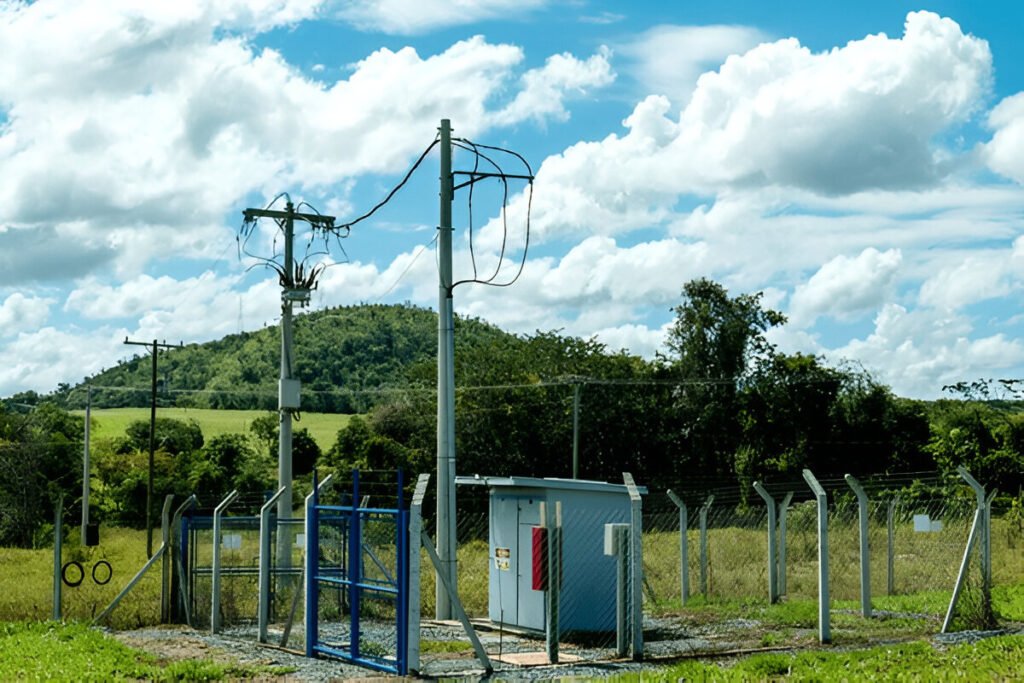
Transformers are essential pieces of equipment in the electrical power grid, enabling the efficient transmission and distribution of electricity over long distances. Overhead distribution transformers, mounted atop utility poles or towers, play a critical role in stepping down high-voltage electricity from transmission lines to levels suitable for local distribution and end-user consumption.
In this article, we will delve into the inner workings, key components, technical specifications, and common configurations of these vital devices that keep our lights on and appliances running.
An overhead distribution transformer is a type of electrical transformer specifically designed for use in overhead power distribution systems. These transformers play a vital role in stepping down the high voltage electricity transmitted over long distances to lower voltage levels suitable for local distribution and end-user consumption.
Overhead distribution transformers are typically mounted on utility poles or towers, hence the term “overhead. They serve as the final step in the electricity distribution process before power reaches homes, businesses, and other facilities connected to the grid.
The working principle of overhead distribution transformers is based on electromagnetic induction. The transformer consists of two electrically isolated coils, the primary and secondary windings, wound around a ferromagnetic core. When an alternating current (AC) is applied to the primary winding, it creates a changing magnetic field in the core. This magnetic field induces an electromotive force (EMF) in the secondary winding, resulting in a transformed voltage level.
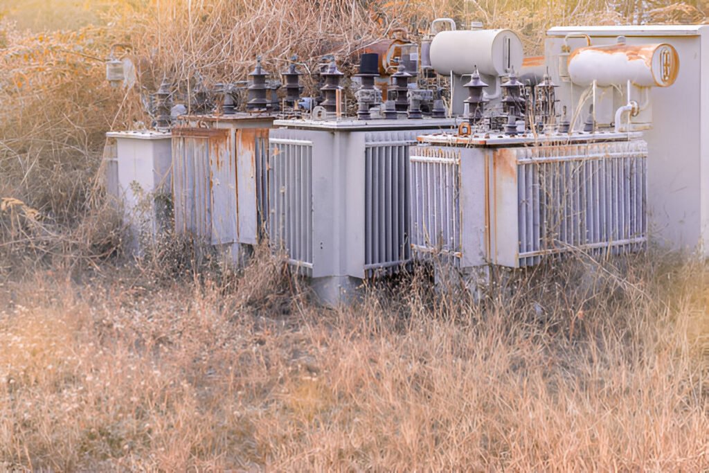
At the heart of an overhead distribution transformer lies the core and coil assembly. The core is typically made of high-quality, grain-oriented silicon steel laminations. These laminations are carefully stacked and arranged to form a closed magnetic circuit, which helps to minimize eddy current losses and improve overall efficiency.
The coils, also known as windings, are made of insulated copper or aluminum conductors. They are precisely wound around the core to create the primary and secondary windings. The primary winding receives the incoming high-voltage electrical energy, while the secondary winding delivers the transformed lower-voltage energy to the distribution network.
The core and coil assembly is housed within a sturdy, weather-resistant tank. The tank serves several important functions, including protecting the internal components from the elements, providing a mounting structure for bushings and other accessories, and facilitating the circulation of insulating oil.
Radiators or cooling fins are often incorporated into the tank design to enhance heat dissipation and maintain optimal operating temperatures. These features help to prolong the life of the transformer and ensure reliable operation under various load conditions.
Insulating oil plays a vital role in the proper functioning and longevity of overhead distribution transformers. The oil serves as both an insulating medium and a cooling agent, helping to prevent electrical breakdown and dissipate heat generated by the core and coil assembly.
The insulating oil is continuously circulated within the transformer tank, typically through natural convection or forced oil cooling systems. This circulation helps to maintain uniform temperature distribution and prevents the formation of hot spots that could lead to insulation breakdown or premature failure.
Overhead distribution transformers are designed to step down high voltage electricity from the transmission grid to lower voltages suitable for local distribution. The primary (high voltage) side typically operates at voltages ranging from 4.16 kV to 34.5 kV. The secondary (low voltage) side then steps this down to common distribution voltages like 120/240V for residential service or 277/480V for commercial applications.
The capacity of overhead distribution transformers, measured in kilovolt-amperes (kVA), indicates how much power the transformer can handle. Residential overhead transformers commonly range from 10 kVA to 50 kVA, serving one to a dozen homes. Larger 100-500 kVA overhead units serve commercial buildings or clusters of homes.
Well-designed overhead distribution transformers can achieve impressive efficiency ratings of 98-99%, meaning very little energy is wasted as heat during the voltage transformation process.
Even with 98%+ efficiency, some energy is still lost as heat. Transformers are submerged in an oil bath and have external cooling fins to dissipate this heat. The oil acts as both a coolant and an electrical insulator, allowing more compact designs.
Power lines are subject to high voltage spikes from lightning strikes or switching surges. Basic Impulse Level (BIL) ratings specify how much surge voltage a transformer can tolerate without damage. BIL is tested by applying a standardized 1.2/50 microsecond voltage wave – this simulates real impulse events.
Overhead distribution transformers typically have BIL ratings of 30kV to 150kV for the low voltage winding and 60kV to 200kV for the high voltage side. Higher system voltages and areas with frequent lightning require higher BIL ratings. The transformer’s insulation system – oil, paper, pressboard, etc. – must be designed to withstand the BIL rating, even as the insulation ages over decades of service.
Single-phase transformers are the most common type for residential and light commercial distribution. As the name implies, they transform a single phase of the three-phase high voltage supply. Typical residential services like 120/240V are fed from one 240V secondary winding with a center tap to provide two 120V legs.
These transformers are often seen mounted alone on utility poles, serving a small cluster of 1-10 homes. The primary high voltage connects between one phase and neutral of the 4-wire distribution feeder. Smaller 10-25 kVA units are used to serve 1-4 homes, while 50 kVA transformers can handle 5-10 homes. Single-phase transformers offer a simple, cost-effective solution for residential loads.
Three-phase transformers are used to serve larger commercial and industrial facilities that require higher power levels and all three phases. These transformers have three sets of primary and secondary windings, one for each phase. The secondary windings can be connected in wye or delta configurations to provide 3-phase power to the building.
Common three-phase commercial services like 277/480V or 120/208V are supplied from overhead three-phase units. The transformers range from around 75 kVA up to 500 kVA or more for the largest buildings. Three separate single-phase transformers can also be banked together to provide three-phase power, but this takes up more pole space.
Three-phase transformers allow utilities to serve large, balanced 3-phase loads efficiently. The three windings are wound on a common core, providing a compact and cost-effective option compared to three individual single-phase units. However, they require more pole space and are heavier, so installation is more involved than for single-phase transformers.
In a wye or star connected transformer, one end of each winding connects to a common neutral point, forming a “Y” shape. The other end of each winding becomes a line terminal – these form the three hot phases. A fourth wire connects to the neutral point for grounding and carrying imbalance currents.
Wye configurations offer several advantages:
Wye connected secondaries are very common for commercial 277/480V services in the USA. The 277V phase-neutral voltage is suitable for lighting and single-phase loads, while 480V phase-phase handles larger 3-phase motor loads.
In a delta connected transformer, the end of one winding connects to the start of the next, forming a triangular loop. There is no neutral point or fourth wire. Each winding becomes one of the three hot phases.
Delta configurations have their own advantages:
However, delta connected transformers can only serve three-phase loads, not single-phase. And they have higher fault current levels since there is no neutral impedance. For these reasons, delta configurations are typically only used on transformer primary windings at distribution voltages.
Learn about electrical transformers, their types, working principles, applications, and maintenance in this comprehensive guide.
Read More
The freezing temperature of mineral oil varies but is typically around -20°C to -40°C (-4°F to -40°F), depending on its composition.
Read More
Auto transformers and distribution transformers differ in voltage levels, applications, and construction for power distribution.
Read More


