Transformers
What Is an Amorphous Core Transformer
Discover the unique properties and applications of amorphous core transformers, a specialized type of electrical transformer.
Read More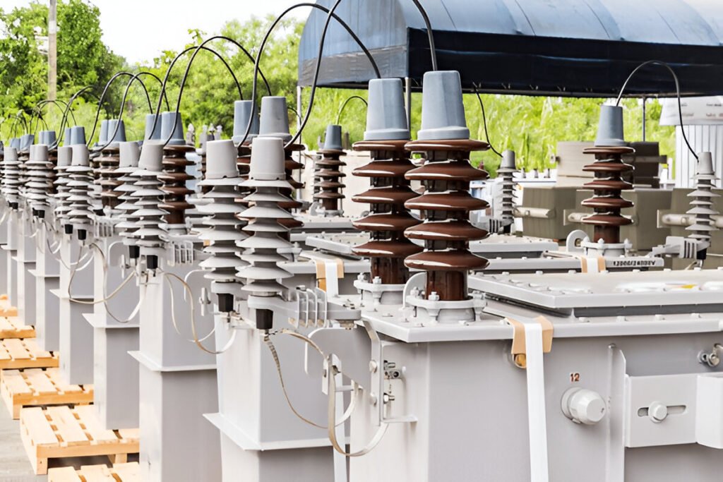
Distribution transformers are essential devices in electrical power distribution networks, responsible for stepping down high voltage from primary distribution lines to lower voltages suitable for end-users. The internal components of a distribution transformer work together to ensure safe, efficient, and reliable operation. This article will provide an in-depth look at the main internal components found within a typical distribution transformer.
The core is the heart of a distribution transformer, providing a low-reluctance path for the magnetic flux generated by the transformer’s windings. It is typically constructed from high-grade, grain-oriented silicon steel laminations, which are stacked and bonded together to form a solid core structure. The laminations are insulated from each other to minimize eddy current losses, which can cause heating and reduce efficiency.
The windings, or coils, are the primary active components in a distribution transformer. They are responsible for the transfer of electrical energy from the primary side to the secondary side through electromagnetic induction. Distribution transformers typically have two sets of windings: the primary winding and the secondary winding.
The primary winding is connected to the high-voltage distribution line and receives the incoming electrical energy. It is designed to handle the higher voltage and lower current of the primary distribution system. The primary winding is usually wound around the core first, with the secondary winding placed concentrically over it.
The conductor used for the primary winding is typically copper or aluminum, chosen based on factors such as cost, conductivity, and weight. The cross-sectional area of the conductor is determined by the rated current of the transformer, ensuring that the winding can handle the required current without overheating.
The secondary winding is connected to the low-voltage side of the transformer and delivers the stepped-down voltage to the end-users. It is designed to handle the lower voltage and higher current required by the connected loads.
Like the primary winding, the secondary winding conductor is also made of copper or aluminum and is sized according to the rated current of the transformer’s secondary side. In some cases, multiple secondary windings may be present to provide different voltage levels for various applications.
The insulation system in a distribution transformer is critical for ensuring safe and reliable operation by preventing electrical short circuits and minimizing dielectric losses. It consists of both liquid and solid insulation components.
Liquid insulation, typically mineral oil or synthetic esters, serves multiple purposes in a distribution transformer. It provides electrical insulation between the windings and the core, as well as between the windings themselves. The liquid insulation also acts as a cooling medium, helping to dissipate heat generated by the transformer’s components.
Solid insulation materials, such as paper and pressboard, are used to provide additional insulation between the windings and the core, as well as between individual winding layers. These materials are impregnated with the liquid insulation to enhance their dielectric properties and improve heat dissipation.
Some distribution transformers are equipped with tap changers, which allow for the adjustment of the transformer’s voltage ratio without interrupting the power supply. Tap changers are used to regulate the output voltage of the transformer, compensating for variations in the primary voltage or changes in load conditions.
There are two main types of tap changers: off-load tap changers (OLTC) and on-load tap changers (OLTC). OLTCs are more common in larger distribution transformers and can adjust the voltage ratio while the transformer is energized and under load. OLTCs, on the other hand, require the transformer to be de-energized before changing the tap position.
Tap changers are typically located on the primary winding side of the transformer and consist of a selector switch that connects to different taps on the winding. By changing the tap position, the number of active turns on the primary winding is altered, effectively changing the transformer’s voltage ratio.
Bushings are insulating structures that provide a means for the primary and secondary windings to be connected to the external circuitry while maintaining electrical isolation from the transformer tank and other components.
High voltage bushings are used to connect the primary winding to the high-voltage distribution line. These bushings are designed to withstand the high electrical stress associated with the primary voltage and are typically made of porcelain or polymeric materials.
The bushing consists of a central conductor, which is connected to the primary winding, surrounded by insulating material. The insulation is designed to provide a long creepage distance between the conductor and the grounded transformer tank, preventing flashover and ensuring reliable operation.
Low voltage bushings are used to connect the secondary winding to the low-voltage distribution network or the end-user’s equipment. These bushings are designed to handle the higher current and lower voltage of the secondary side and are typically made of porcelain or epoxy resin.
The low voltage bushings are usually smaller in size compared to the high voltage bushings and may be located on the side or cover of the transformer tank, depending on the design and application requirements.
The transformer tank serves as a protective enclosure for the core, windings, and insulation system. It is typically made of welded steel plates and is designed to withstand the mechanical stresses associated with the transformer’s operation, as well as environmental factors such as weather and corrosion.
The tank also acts as a reservoir for the liquid insulation, providing a means for heat dissipation and maintaining a stable operating temperature for the transformer’s components.
To enhance heat dissipation, distribution transformers are often equipped with cooling fins or radiators. These components are attached to the exterior of the transformer tank and increase the surface area available for heat exchange with the surrounding air.
Cooling fins are typically welded or bolted to the tank walls and are designed to optimize air flow and maximize heat transfer. In some cases, fans may be used in conjunction with the cooling fins to improve cooling efficiency, particularly in high-capacity transformers or in environments with limited natural air circulation.
As the transformer operates and generates heat, the liquid insulation expands and contracts. To accommodate these changes in volume and maintain proper insulation levels, the transformer tank is equipped with an oil expansion and preservation system.
This system typically consists of an expansion tank or conservator, which is connected to the main transformer tank through a pipe or hose. As the insulation liquid expands, it flows into the conservator, and as it contracts, the liquid is drawn back into the main tank. This process helps to maintain a constant pressure within the transformer and prevents the ingress of moisture and other contaminants.
In some transformer designs, a nitrogen blanket or a sealed tank system may be used instead of a conservator. These systems help to minimize the exposure of the insulation liquid to the atmosphere, reducing the risk of oxidation and contamination.
Distribution transformers are often equipped with various accessories that help to ensure safe, reliable, and efficient operation. Some of the most common accessories include:
A pressure relief device, also known as a pressure relief valve or a rupture disk, is a safety component designed to protect the transformer from excessive internal pressure. In the event of an internal fault or abnormal operating condition that causes a rapid increase in pressure, the relief device will open and allow the pressurized gas or liquid to escape, preventing the tank from rupturing.
An oil level gauge is used to monitor the level of liquid insulation within the transformer tank. It provides a visual indication of the insulation level and helps to detect any leaks or changes in the insulation volume over time. The gauge is typically mounted on the side of the tank or on the conservator and may be equipped with a sight glass or a graduated scale for easy reading.
A temperature gauge is used to monitor the operating temperature of the transformer. It is typically mounted on the top or side of the tank and consists of a sensing element, such as a resistance temperature detector (RTD) or a thermocouple, which is immersed in the insulation liquid.
The temperature gauge provides a visual indication of the transformer’s temperature and may be equipped with contacts for triggering alarms or initiating protective actions, such as activating cooling fans or tripping the transformer in case of overheating.
A breather is a device that allows for the exchange of air between the transformer tank and the surrounding atmosphere while preventing the ingress of moisture and contaminants. It is typically mounted on the conservator or the main tank and consists of a desiccant chamber filled with silica gel or other moisture-absorbing materials.
As the transformer operates and the insulation liquid expands and contracts, air is drawn into or expelled from the tank through the breather. The desiccant material absorbs any moisture from the incoming air, ensuring that the insulation liquid remains dry and free from contaminants.
An earthing or grounding terminal is a connection point on the transformer tank that is used to connect the tank to the substation grounding system. This connection ensures that the tank remains at the same potential as the ground, preventing the buildup of static charges and reducing the risk of electrical shock or equipment damage.
The earthing terminal is typically a stud or a pad welded to the base of the tank, and it is connected to the substation grounding grid using a suitable conductor, such as copper wire or flat braids.
Discover the unique properties and applications of amorphous core transformers, a specialized type of electrical transformer.
Read More
When you’re working with three-phase systems, understanding delta transformers is crucial. They’re not only efficient in voltage transformation and electrical isolation, but they also offer unique advantages in load balancing and power distribution. However, delta transformers come with their own set of challenges that you must consider. In this comprehensive guide, we’ll explore the fundamentals […]
Read More
Distribution transformers can fail due to overloading, insulation breakdown, lightning strikes, or manufacturing defects.
Read More


