Transformers
Common Causes of Transformer Explosion
Explore the primary reasons behind transformer explosions, from overloading to insulation failure and more.
Read More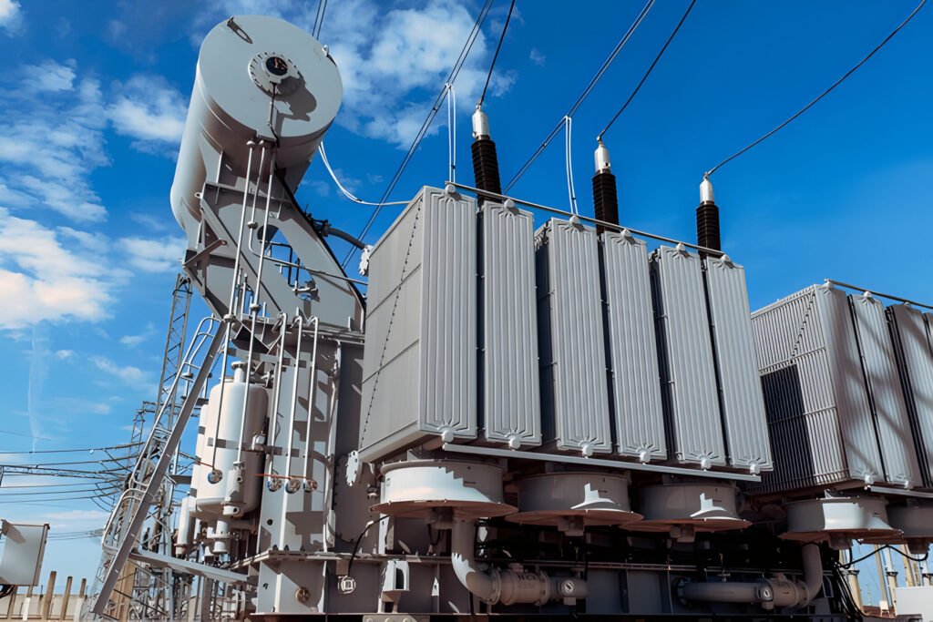
A distribution transformer is a crucial component in the electrical power distribution system, designed to step down high-voltage electricity from transmission lines to lower voltages suitable for end-user consumption. These transformers are the final link in the power grid, delivering electricity to homes, businesses, and industrial facilities.
Distribution transformers typically operate at voltages ranging from 4 kV to 34.5 kV on the primary side and reduce this to 120/240 V or 480 V on the secondary side for residential and commercial use. They come in various sizes and configurations, including single-phase and 3-phase transformer models, to meet different power requirements.
Distribution transformers operate on the principle of electromagnetic induction to transform high-voltage electricity from primary distribution lines to lower voltage levels suitable for end-user consumption.
The transformation process begins when high-voltage electricity enters the primary windings of the distribution transformer. These windings are typically made of copper wire, wrapped around an iron core. As alternating current flows through the primary windings, it creates a fluctuating magnetic field in the core.
This magnetic field then induces a voltage in the secondary windings, which are also wrapped around the same iron core. The number of turns in the primary and secondary windings determines the voltage transformation ratio. For example, if the primary winding has 100 turns and the secondary winding has 10 turns, the voltage will be stepped down by a factor of 10.
The core is a fundamental component of a distribution transformer, typically constructed from laminated silicon steel sheets. The core’s primary function is to provide a low-reluctance path for magnetic flux, enhancing the transformer’s efficiency.
In modern distribution transformers, manufacturers often use advanced core materials such as amorphous metals to reduce core losses. These materials can significantly improve the transformer’s energy efficiency, particularly in no-load conditions.
Windings are consisting of primary and secondary coils. These coils are usually made of copper wire, chosen for its excellent electrical conductivity. The primary windings receive the high-voltage input, while the secondary windings deliver the stepped-down voltage output.
The design and arrangement of these windings directly impact the transformer’s voltage transformation ratio and overall performance. In some cases, aluminum may be used instead of copper for cost considerations, though this can affect the transformer’s efficiency and power ratings.
Distribution transformers, particularly oil-filled types, require tanks to house the core, windings, and insulating oil. These tanks are typically made of steel and designed to withstand internal pressure changes due to oil expansion and contraction during operation.
Many tanks feature radiators or fins to increase surface area and improve cooling. For pole-mounted transformers, tanks are often compact and cylindrical to fit the limited space available.
Bushings are insulating devices that allow electrical conductors to pass safely through the transformer tank. They provide a connection point between the internal windings and the external power lines. Bushings are typically made of porcelain or polymer materials with high dielectric strength to prevent electrical breakdown.
In distribution transformers, bushings are designed to withstand the specific voltage ratings of the transformer and provide protection against environmental factors such as moisture and contamination.

Single phase distribution transformers are commonly used in residential areas and light commercial applications. These transformers are designed to handle lower power loads and are typically found in pole-mounted configurations. They convert high-voltage electricity from primary distribution lines to lower voltages suitable for household use.
Three phase distribution transformers, also known as 3-phase transformers, are more commonly used in industrial and heavy commercial settings. These transformers can handle higher power loads and are more efficient for large electrical equipment. They are often found in pad-mounted or vault-mounted configurations.
Pad-mounted transformers are ground-level installations often seen in residential neighborhoods and commercial areas. These units are enclosed in a tamper-resistant steel cabinet and are typically oil-filled for cooling.
Pole-mounted transformers are a common sight on utility poles in many areas. These transformers are usually single-phase and are designed to serve a small number of homes or businesses. Pole-mounted transformers are exposed to the elements and must be built to withstand various weather conditions. Pole-mounted transformers are widely used in rural areas and suburban neighborhoods where overhead power lines are prevalent.
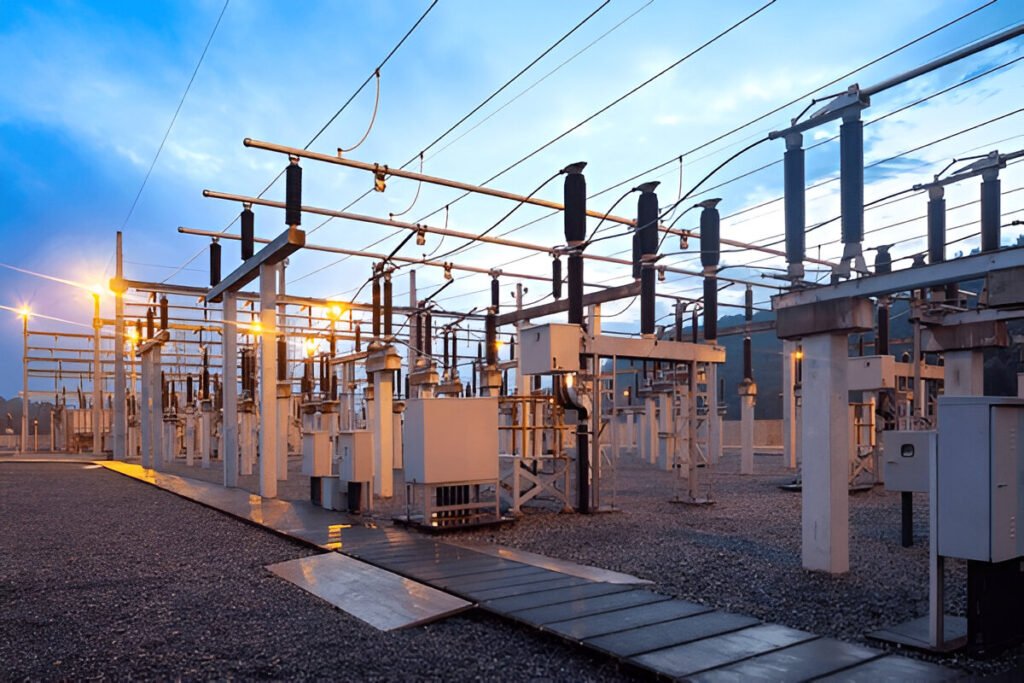
Underground vault mounted transformers are installed below ground level, typically in urban areas where space is at a premium. These transformers are protected from the elements and vandalism but require special considerations for cooling and maintenance access.
Liquid-immersed transformers use oil or other dielectric fluids for insulation and cooling. Transformer oil helps dissipate heat generated during operation and provides excellent insulation properties. These transformers are often more efficient and can handle higher loads compared to dry-type transformers.
Dry-type distribution transformers do not use any liquid for cooling or insulation. Instead, they rely on air circulation for cooling. These transformers are often used in indoor applications where fire safety is a concern, such as in commercial buildings or industrial facilities.

In residential applications, distribution transformers are typically located near property lines or in utility easements. For commercial buildings, transformers may be installed in dedicated electrical rooms or outdoor enclosures.
The primary and secondary windings of distribution transformers can be connected in various configurations to meet specific voltage and current requirements.
The most common connection types for distribution transformers include:
For single-phase distribution transformers, the connections are simpler:
Distribution transformers, while essential components of the power grid, are not 100% efficient in their operation. These devices experience two main types of losses: no-load (core) losses and load (winding) losses.
No-load losses, also known as core losses, occur in a distribution transformer even when it is energized but not supplying any load. These losses are primarily due to the alternating magnetic field in the transformer’s iron core. The main contributors to core losses are:
To minimize core losses, transformer manufacturers use high-quality core materials such as grain-oriented silicon steel or amorphous metals. These materials have lower hysteresis and eddy current losses compared to traditional core materials. Additionally, the core is constructed using thin laminations to reduce eddy currents further.
Load losses, also called copper losses or winding losses, occur when the distribution transformer is supplying power to a load. These losses are primarily due to the resistance of the copper windings and increase with the square of the current flowing through them. The main components of load losses are:
To reduce load losses, transformer designers optimize the winding design, use high-quality copper conductors, and employ techniques such as transposition of conductors in larger transformers.
The total losses in a distribution transformer are the sum of no-load and load losses. These losses not only reduce the overall efficiency of the transformer but also generate heat, which can affect the transformer’s lifespan and performance. Transformer manufacturers strive to balance these losses to achieve optimal efficiency across various loading conditions.

These transformers, often pole-mounted transformers or pad-mounted transformers, step down high-voltage electricity from primary distribution lines to levels suitable for household use, typically 120/240 volts in North America.
In residential applications, single-phase transformers are commonly used. These units can handle the power requirements of multiple homes, ranging from 10 to 50 kVA.
Light commercial establishments, such as small offices, retail stores, and restaurants, typically require larger distribution transformers than residential areas. These transformers are often three-phase units with capacities ranging from 75 to 500 kVA.
Pad-mount transformers are frequently used in light commercial settings due to their compact design and ability to be placed near buildings. These transformers provide the necessary power for lighting, HVAC systems, and various electrical equipment used in commercial buildings.
Heavy commercial and industrial applications demand more robust distribution transformers to handle higher power requirements. These settings often use three-phase transformers with capacities ranging from 500 kVA to several MVA.
Industrial facilities may require multiple transformers to support various processes and equipment. Oil-filled transformers are commonly used in these applications due to their superior cooling capabilities and ability to handle higher loads.
Several factors are considered when determining the appropriate transformer size:
Distribution transformers and power transformers differ significantly in size and insulation levels. Distribution transformers are generally smaller, with power ratings typically ranging from 5 kVA to 5000 kVA. They operate at lower voltage levels, usually below 35 kV. In contrast, power transformers are much larger, with ratings that can exceed 1000 MVA and voltage levels up to 765 kV or higher.
The insulation level of these transformers also varies. Distribution transformers have a lower Basic Impulse Insulation Level (BIL) compared to power transformers. This is because they operate at lower voltages and are not required to withstand the same level of electrical stress. Power transformers, on the other hand, require higher insulation levels due to their operation at higher voltages.
In distribution transformers, iron losses are typically higher in proportion to the total losses. This is because distribution transformers often operate at partial load conditions, where core losses remain constant regardless of the load.
Power transformers, due to their larger size and higher operating voltages, tend to have higher copper losses. These losses are more significant at full load conditions, which is typical for power transformers in transmission systems. To minimize copper losses, power transformers often use larger conductor cross-sections and advanced cooling systems.
Distribution transformers typically reach their maximum efficiency at lower load levels, often around 50% of their rated capacity. This is because they are designed to operate efficiently under varying load conditions throughout the day.
Power transformers, in comparison, are designed to operate at higher efficiency levels at full load or near-full load conditions. This is due to their role in transmitting large amounts of power over long distances, where consistent high loads are more common.
Explore the primary reasons behind transformer explosions, from overloading to insulation failure and more.
Read More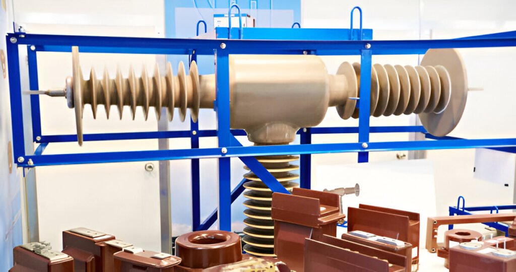
Explore the various types of dry type transformers, including cast resin, vacuum pressure impregnated (VPI), and open wound designs.
Read More
Discover the key components and inner workings at the heart of transformer neural networks used for NLP tasks.
Read More


