Transformers
What Is the Life Expectancy of a Dry Type Transformer
The life expectancy of a dry type transformer typically ranges from 30 years to over 40 years.
Read More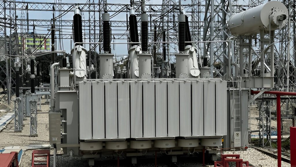
In the realm of electrical power systems, power transformers reign supreme as the backbone of efficient energy transmission and distribution. These colossal devices, often weighing tens of tons, leverage the principles of electromagnetic induction to seamlessly step up or step down voltage levels, enabling the transfer of electrical energy over vast distances with minimal losses.
The intricate design and construction of power transformers involve a complex interplay of electrical, magnetic, and thermal considerations, necessitating the expertise of skilled engineers and technicians. By delving into the inner workings, applications, and maintenance aspects of these essential machines, we aim to provide a comprehensive understanding of their pivotal role in the modern power grid.
Power transformers are electrical devices that transfer electrical energy between two or more circuits through electromagnetic induction. They are designed to step up or step down voltage levels, enabling the efficient transmission of electrical power over long distances.
The primary function of a power transformer is to convert electrical energy from one voltage level to another. This is achieved by utilizing the principle of electromagnetic induction between two or more coils of wire, known as windings. The primary winding receives the input voltage, while the secondary winding(s) output the transformed voltage.
The operation of power transformers relies on the principle of electromagnetic induction, where a changing magnetic field induces an electromotive force (EMF) in a conductor.
At the core of a power transformer, there are two or more coils of insulated wire called windings. The primary winding is connected to the input voltage source, while the secondary winding delivers the output voltage to the load. When an alternating current (AC) flows through the primary winding, it creates a changing magnetic field in the transformer’s core.
This changing magnetic field induces an EMF in the secondary winding, causing a current to flow in the secondary circuit. The voltage induced in the secondary winding depends on the ratio of the number of turns in the primary and secondary coils. If the secondary winding has more turns than the primary, it acts as a step-up transformer, increasing the output voltage.
Conversely, if the secondary winding has fewer turns than the primary, it acts as a step-down transformer, reducing the output voltage.
The core is a critical component of power transformers, serving as the magnetic circuit that facilitates the transfer of electrical energy between the primary and secondary windings. It is typically made of high-quality, grain-oriented silicon steel laminations, which help to minimize core losses, such as hysteresis and eddy current losses.
The windings are consisting of the primary and secondary coils. These coils are made of insulated copper or aluminum conductors and are responsible for the transformer’s voltage transformation and current flow.
The primary winding is connected to the input voltage source, while the secondary winding delivers the transformed voltage to the load. The turns ratio between the primary and secondary windings determines the voltage step-up or step-down ratio of the transformer.
Insulation ensures safe and reliable operation by preventing electrical short circuits and minimizing leakage flux. Various insulation materials are used, including mineral oil, paper, and epoxy resin, depending on the transformer type and application.
Mineral oil serves as both an insulating and cooling medium in oil-immersed transformers, while dry-type transformers rely on air and solid insulation materials.
Bushings are the electrical connection points that allow the primary and secondary windings to be connected to the external power system. They are designed to withstand high voltages and currents while providing reliable electrical insulation between the transformer’s internal components and the outside environment.
Tap changers are mechanical devices used to regulate the output voltage of power transformers under varying load conditions. They allow for fine adjustments to the transformer’s turns ratio, enabling voltage control and maintaining a stable supply of electrical power to the connected load.
There are two main types of tap changers: on-load tap changers (OLTC) and off-load tap changers (DETC). OLTCs can adjust the voltage while the transformer is energized and under load, while DETCs require the transformer to be de-energized before making any adjustments.
The cooling system is an essential component of power transformers, responsible for dissipating the heat generated during operation.
Oil-immersed transformers typically use a combination of natural or forced oil circulation and air cooling, while dry-type transformers rely on air cooling or water-cooling systems.
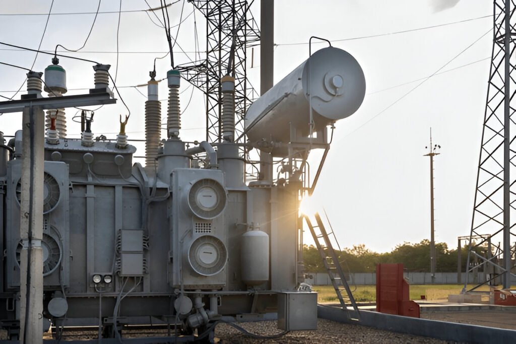
The transformer tank is a steel enclosure that houses the core, windings, insulation, and cooling medium (oil or gas). It serves to protect the internal components from the external environment and contains any leaks or spills.
In oil-immersed transformers, the conservator is an additional component mounted on top of the main tank. It acts as an oil expansion reservoir, allowing for the expansion and contraction of the insulating oil due to temperature changes, thus maintaining a constant oil level within the main tank.


Step-up transformers are designed to increase the voltage level from the primary winding to the secondary winding. This type of transformer is commonly used in power generating stations to boost the voltage for efficient long-distance transmission of electrical energy. By increasing the voltage, step-up transformers help minimize power losses during transmission.
Step-down transformers work in the opposite manner, reducing the voltage from the primary winding to the secondary winding. These transformers are used to decrease high transmission voltages to lower levels suitable for distribution networks and end-user equipment.
Single-phase transformers are designed to operate with a single phase of AC voltage. They are commonly used in low-power applications, such as household appliances, lighting systems, and small electronic devices. Single-phase transformers typically have one primary winding and one secondary winding, allowing for simple voltage step-up or step-down functionality.
Three-phase transformers are used in high-power applications, such as industrial facilities and power distribution systems. These transformers have three sets of primary and secondary windings, each corresponding to one phase of a three-phase AC supply.
Isolation transformers provide electrical isolation between the primary and secondary circuits, without changing the voltage level. They are designed to protect sensitive electronic equipment from voltage spikes, noise, and other disturbances in the power supply. Isolation transformers also help prevent electric shock hazards by isolating the equipment from the main power source.
Autotransformers have a single winding that serves as both the primary and secondary winding. A portion of the winding is used as the primary, while the entire winding acts as the secondary. Autotransformers are more compact and economical compared to conventional two-winding transformers, making them suitable for applications where adjustable voltage levels are required, such as in motor starters and voltage regulators.
Dry-type transformers use air or an inert gas as the cooling medium instead of oil. They are designed for indoor installations where fire safety is a concern, such as in commercial buildings, hospitals, and schools. Dry-type transformers are also environmentally friendly and require less maintenance compared to oil-filled transformers.
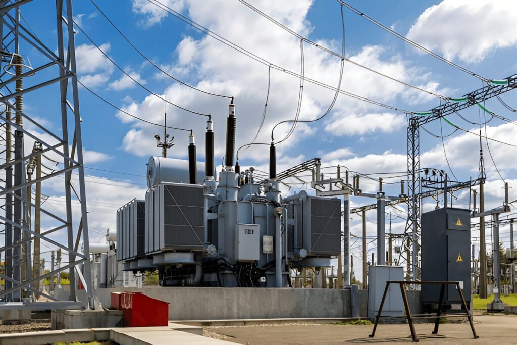
Oil-filled transformers use transformer oil as a cooling medium and insulating material. The oil helps dissipate heat generated by the transformer’s core and windings, allowing for higher power ratings and improved efficiency. Oil-filled transformers are commonly used in outdoor substations and industrial applications where high power capacity and reliability are essential.
Power transformers are highly efficient electrical devices, with most modern designs achieving efficiency levels above 98%.
By using electromagnetic induction, transformers can step up or step down the voltage as needed, enabling the efficient transmission of electrical energy over long distances.
Power transformers provide electrical isolation between the primary and secondary windings, which is crucial for safety and protection. The primary and secondary circuits are electrically separated, with the only connection being the magnetic flux in the core.
Power transformers offer inherent overload protection due to their inductive properties. When the load current exceeds the rated value, the transformer’s magnetic core begins to saturate, limiting the current flow and preventing damage to the transformer and connected equipment.
Power transformers are designed to be highly reliable and durable, with many units providing dependable service for decades.
Transformer losses are an inherent part of the power transformation process. They arise from the physical properties of the transformer components and the electromagnetic principles governing their operation. While transformers are designed to minimize these losses, they cannot be eliminated entirely.
The primary sources of transformer losses are the copper windings, the magnetic core, and the insulation materials. Each of these components contributes to specific types of losses that collectively impact the overall efficiency of the transformer.
Copper loss, also known as I²R loss, occurs due to the resistance of the copper windings in the transformer. As current flows through the primary and secondary windings, it encounters resistance, causing power dissipation in the form of heat.
Hysteresis loss occurs in the magnetic core of the transformer. When the magnetic field in the core alternates due to the AC supply, the magnetic domains in the core material experience realignment. This realignment requires energy, which is dissipated as heat.
Eddy current loss occurs in the magnetic core of the transformer due to induced currents. When the magnetic flux changes in the core, it induces circulating currents within the core material. These circulating currents, known as eddy currents, generate heat and contribute to power loss.
Flux loss, also known as leakage flux loss, occurs due to the leakage of magnetic flux from the core. Not all the magnetic flux generated by the primary winding links with the secondary winding. Some flux lines escape the core and do not contribute to the energy transfer between the windings.

The life expectancy of a dry type transformer typically ranges from 30 years to over 40 years.
Read More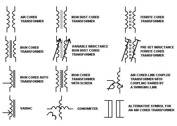
The transformer symbols is a standardized representation of the transformer in the circuit diagram and plays a key role. As they help engineers and technicians understand and analyze complex electrical circuits. In this article, we will delve into the world of transformer symbol, exploring their types, applications, and how to distinguish between them. Introduction to […]
Read More
Learn about the roles of ground and neutral wires in electrical systems and how they ensure safety and proper functioning.
Read More


