Transformers
What Is Transformer Impedance
Transformer impedance is a crucial factor that affects voltage regulation, short-circuit current, and power transfer efficiency.
Read More
Distribution transformers are connected through various physical and electrical configurations. On the primary side, they receive high voltage, while the secondary side delivers lower voltage. Common connection types include Star-Star, Delta-Delta, Star-Delta, and Delta-Star. These transformers can be pole-mounted, pad-mounted, or vault-mounted, depending on the installation requirements.
The primary side of a distribution transformer is connected to the high voltage power distribution network. This connection is typically made using specialized connectors and insulation systems designed to handle the higher voltages present on the primary side.
Distribution transformers commonly use one of two types of primary side connections:
The primary side connection often includes protective devices such as fuses or circuit breakers to safeguard the transformer from overcurrent or short circuit conditions. These protective devices are typically mounted externally on the transformer tank or on nearby poles.
The secondary side of a distribution transformer is where the low voltage output is connected to the electrical distribution system.
On the secondary side, the transformer typically steps down the voltage to standard utilization levels, which are commonly 120/240 volts for single-phase systems or 208Y/120 volts and 480Y/277 volts for three-phase systems in North America.
The secondary winding of the transformer is usually connected in one of two configurations:

The Star-Star (Y-Y) connection is a common configuration for distribution transformers. In this arrangement, both the primary and secondary windings are connected in a star (or wye) formation. Each winding has one end connected to a common point, forming a neutral, while the other ends are connected to the phase conductors.
In a Delta-Delta (D-D) connection, both primary and secondary windings are arranged in a triangular configuration. This connection type does not provide a neutral point on either side of the transformer.
The Star-Delta (Y-D) connection combines a star-connected primary winding with a delta-connected secondary winding. This configuration is commonly used to step down voltage in distribution systems.
The Delta-Star (D-Y) connection is the inverse of the Y-D configuration, with a delta-connected primary and a star-connected secondary. This arrangement is frequently used in step-up transformers for power transmission.
The Delta-Wye (Δ-Y) connection type combines a delta-connected primary winding with a wye-connected secondary winding.
In the primary (delta) side, the three windings are connected in a triangular formation. Each winding is connected between two phase conductors, with no neutral point. This configuration offers advantages in harmonic suppression and fault tolerance.
The secondary (wye) side features three windings connected in a star formation. One end of each winding is joined at a common point, forming the neutral. The other ends connect to the phase conductors. This arrangement provides a neutral point for single-phase loads and allows for both line-to-line and line-to-neutral voltages.
Key characteristics of the Delta-Wye connection include:
Delta-Wye connections are widely used in power distribution systems due to their versatility and ability to accommodate both three-phase and single-phase loads efficiently.
In Wye-Wye (Y-Y) connection, both the primary and secondary windings are connected in a wye (star) configuration.
The Y-Y connection offers several advantages:
The Y-Y connection does have some limitations:
To address these limitations, Y-Y transformers often incorporate design features such as five-limb cores or tertiary windings. These modifications help improve performance and stability under various operating conditions.
Y-Y transformers are commonly used in medium-voltage distribution systems, particularly in areas with predominantly single-phase loads. They are also employed in some industrial applications where a balanced three-phase supply is required.
In Delta-Delta (Δ-Δ) connection, both the primary and secondary windings are connected in a delta configuration.
In a Delta-Delta connection, the primary windings are connected end-to-end to form a closed triangle, with each corner of the triangle representing a phase. The same configuration is applied to the secondary windings. This connection method offers several advantages and characteristics:
The Delta-Delta connection is commonly used in industrial applications, particularly where motor loads are prevalent. It is also frequently employed in power distribution systems where the ability to continue operation under single-phase fault conditions is valued.

Single-phase transformer connections are widely used in residential and light commercial applications to step down the voltage from distribution lines to usable levels for end-users. These connections involve two primary configurations: center-tapped and non-center-tapped transformers.
Center-tapped transformers have a secondary winding with a center tap, creating two equal voltage outputs. This configuration provides 240 volts across the entire secondary winding and 120 volts from each end to the center tap. Center-tapped transformers are common in North American residential systems, allowing for both 240V and 120V service.
Non-center-tapped transformers have a single secondary winding without a center tap. These transformers typically provide a single voltage output, such as 230V or 240V, and are more common in countries using 230V as the standard residential voltage.
The primary side of single-phase transformers is connected to one phase and neutral of the distribution system. The secondary side connections depend on the transformer type and the required output voltage:
Single-phase transformers may be connected in various configurations to meet specific voltage requirements:
Grounding connects the transformer’s neutral point or metal enclosure to the earth. This connection provides a low-impedance path for fault currents, limiting voltage rise during ground faults. Proper grounding helps protect personnel from electric shock and prevents damage to equipment.
Bonding involves connecting conductive parts of the transformer system to create an equipotential plane. This practice reduces voltage differences between metal components, minimizing the risk of electric shock and stray currents.
Distribution transformers typically employ a grounded wye configuration on the secondary side. The neutral point is connected to a grounding electrode system, which may include ground rods, building steel, or concrete-encased electrodes.
The primary side grounding depends on the utility’s distribution system. In some cases, the primary neutral is grounded at the transformer, while in others, it remains ungrounded.
Transformer tanks and enclosures are bonded to the grounding system to ensure safety. This connection prevents the buildup of static charges and provides a path for fault currents if insulation failure occurs.

Pole-mounted transformers are commonly used in rural and suburban areas where overhead power lines are prevalent. These transformers are attached to utility poles at a height of approximately 20 to 30 feet above ground level. The elevated position helps protect the transformer from potential damage and unauthorized access.
Pole-mounted transformers typically have a cylindrical shape and are equipped with mounting brackets for secure attachment to the utility pole. They are designed to withstand various weather conditions, including high winds and ice accumulation.
Pad-mounted transformers are ground-level installations commonly used in urban and suburban areas with underground power distribution systems. These transformers are housed in weatherproof metal enclosures and placed on concrete pads.
The enclosures are designed with lockable doors to prevent unauthorized access and maintain safety. Pad-mounted transformers are often used in residential neighborhoods, commercial areas, and industrial complexes.
Vault-mounted transformers are installed in underground vaults or chambers, typically in dense urban areas or locations where space is limited above ground. These transformers are housed in specially designed, reinforced concrete structures that protect them from environmental factors and potential flooding.
Vault-mounted transformers require careful design considerations for ventilation, cooling, and access for maintenance. They are often used in high-rise buildings, underground parking structures, and other areas where above-ground installations are not feasible or desirable.

Transformer impedance is a crucial factor that affects voltage regulation, short-circuit current, and power transfer efficiency.
Read More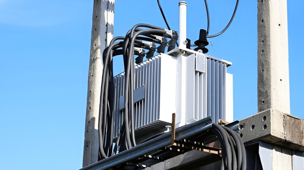
Explore the causes of excessive neutral current, including unbalanced loads, harmonics, and wiring issues, in this concise overview.
Read More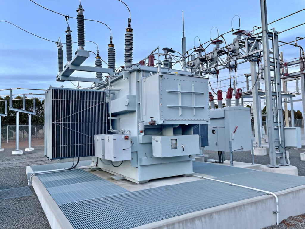
A three-phase transformer is a device that transfers electrical energy between two or more three-phase circuits.
Read More


