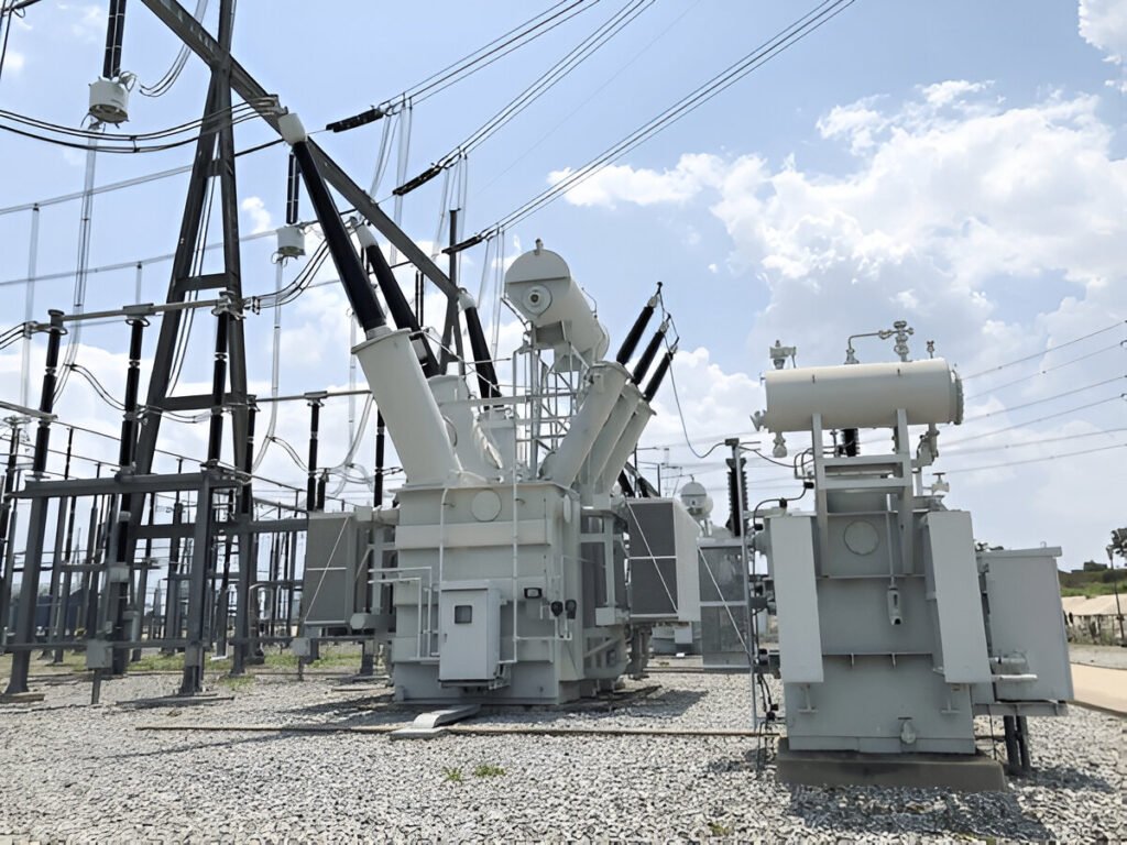
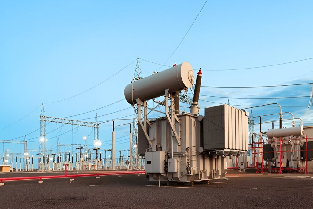
What Is All Day Efficiency in Distribution Transformers
All day efficiency measures a distribution transformer’s average efficiency at varying load levels over 24 hours.
Read More
In the electrical power industry, transformers function as vital components for the transmission and distribution of electricity. Two common types of transformers, potential transformers (PTs) and voltage transformers (VTs), are often used interchangeably but serve distinct purposes.
This blog post will delve into the technical differences between PTs and VTs, focusing on their construction, application, and performance characteristics within electrical systems.

A voltage transformer (VT) is a type of transformer designed to measure voltage in an electrical power system. VTs are used in both low and high voltage applications to safely and accurately monitor the voltage levels in a circuit. These transformers step down the high voltage of the primary circuit to a lower, safer level suitable for measuring devices or protective relays.
The primary winding of a voltage transformer is connected in parallel with the circuit being measured, while the secondary winding provides a proportional voltage output. The turns ratio between the primary and secondary windings determines the voltage step-down ratio.
A potential transformer (PT) is essentially the same device as a voltage transformer. The terms “potential transformer” and “voltage transformer” are often used interchangeably in the electrical power industry. PTs are instrumental in measuring and monitoring voltage levels in both low and high voltage systems.
Like voltage transformers, potential transformers feature a primary winding connected in parallel with the circuit being measured and a secondary winding that provides a stepped-down voltage output. This voltage reduction allows for safe and efficient measurement and monitoring of high voltage systems using standard low voltage measuring devices.

While potential transformers (PTs) and voltage transformers (VTs) are both types of instrument transformers used to step down high voltages to measurable levels, they have several key differences in terms of function, accuracy, design, and applications.
The primary function of a potential transformer is to provide a scaled-down voltage output proportional to the high voltage input, allowing for safe and accurate measurement of high voltages in electrical systems. In contrast, voltage transformers are designed to provide a voltage output that is electrically isolated from the high voltage input, making them suitable for powering protective relays, meters, and other low-voltage devices.
Potential transformers are designed to provide highly accurate voltage measurements, typically with accuracy classes ranging from 0.1 to 1.0 according to international standards such as IEC 61869-3. On the other hand, voltage transformers prioritize electrical isolation over measurement accuracy, with typical accuracy classes ranging from 1.0 to 3.0 as per IEC 61869-3.
Potential transformers are constructed with high-quality magnetic cores and windings to minimize errors and ensure accurate voltage measurements. They often feature multiple secondary windings to provide different voltage ratios and facilitate connection to various measuring devices. In contrast, voltage transformers have a simpler design focused on providing reliable electrical isolation. They may have a single secondary winding and are built with insulation materials suitable for the intended voltage level.
Due to their high accuracy, potential transformers are primarily used in metering applications, such as energy metering in substations, power plants, and industrial facilities. They provide precise voltage measurements for billing, load monitoring, and power quality analysis. Voltage transformers, with their emphasis on electrical isolation, are commonly used in protective relaying applications, where they supply voltage signals to protective devices like overcurrent relays, distance relays, and voltage-based protection schemes, ensuring the safe operation of electrical systems.

At their core, potential transformers (PTs) and voltage transformers (VTs) are both types of transformers. They operate on the principle of electromagnetic induction, where an alternating current in the primary winding induces a proportional voltage in the secondary winding. This allows them to step down high voltages to lower, more manageable levels suitable for measuring instruments or protective relays.
PTs and VTs are designed to measure voltage in electrical systems. They provide a scaled-down representation of the primary voltage, allowing accurate monitoring and analysis of voltage levels without directly connecting measurement devices to high-voltage circuits.
Another key similarity between PTs and VTs is their ability to provide isolation and protection. The transformer design physically separates the primary and secondary windings, creating an insulation barrier. This isolation protects measuring instruments and personnel from the high voltages present in the primary circuit. By isolating the secondary circuit, PTs and VTs enhance safety and prevent damage to sensitive equipment.
PTs and VTs serve as an interface between high-voltage systems and measuring instruments or protective relays. They allow these devices to be connected to the low-voltage secondary circuit, enabling accurate measurement and monitoring of electrical parameters. The transformer’s secondary winding provides a safe and convenient connection point for instruments such as voltmeters, watt meters, and relays, facilitating effective system monitoring and control.
Both PTs and VTs are available in standardized voltage ratios. These ratios define the relationship between the primary and secondary voltages. Common ratios include 110V/√3:110V/√3 and 110V/√3:100V/√3. The standardized ratios ensure compatibility with measuring instruments and allow for consistent voltage measurements across different electrical systems.