Transformers
What Is the Difference Between Open and Closed Delta
When comparing open and closed delta configurations, learn which system delivers optimal power capacity and reliability for your electrical needs.
Read More
From the massive units in power plants to the tiny ones in your electronic devices, transformers come in diverse types, each designed for specific purposes.
In this comprehensive guide, we’ll explore the different classifications of transformers based on their voltage transformation, core construction, materials, applications, cooling medium, and phases.
Step-up transformers increase the voltage of an alternating current (AC) power supply. They have a primary winding with fewer turns than the secondary winding. The voltage transformation ratio depends on the number of turns in each winding. Step-up transformers are used in power transmission systems to minimize power losses during long-distance transmission. Power plants generate electricity at relatively low voltages, typically between 11 kV and 33 kV. The voltage is stepped up to levels often exceeding 400 kV for efficient power transfer over vast distances.
Step-down transformers decrease the voltage of an AC power supply. They have a primary winding with more turns than the secondary winding. The voltage transformation ratio is the inverse of that in step-up transformers. Step-down transformers are used to reduce high transmission voltages to levels suitable for distribution to end-users. The high voltage is progressively stepped down to 132 kV, 66 kV, 33 kV, 11 kV, and finally to the low-voltage levels of 220V or 110V for household and industrial use. This multi-stage voltage transformation ensures safe and efficient power delivery to consumers.
Isolation transformers provide electrical isolation between the primary and secondary windings. They have a 1:1 turns ratio, meaning the input and output voltages are the same. The primary purpose of isolation transformers is to protect against electric shock and reduce electrical noise. They are commonly used in medical equipment, electronic devices, and in situations where electrical safety is paramount. Isolation transformers prevent direct current (DC) from passing through, while allowing AC to be coupled from the primary to the secondary winding. This isolation helps to prevent ground loops and reduces the risk of equipment damage due to voltage spikes or surges.
Core-type transformers feature a single magnetic core, typically in the shape of a rectangular frame or a cruciform. The primary and secondary windings are wound around opposite legs of the core, with the low-voltage winding placed closer to the core and the high-voltage winding on the outside. This arrangement minimizes leakage flux and improves coupling between the windings.
The core is constructed from laminated silicon steel sheets, which are insulated from each other to reduce eddy current losses. The steel used in the core has high magnetic permeability, allowing for efficient magnetic flux transfer between the windings. Cooling ducts are often provided between the core and the windings to dissipate heat generated during operation.
Core-type transformers are commonly used in power and distribution applications, as they offer good voltage regulation and efficiency. They are suitable for low to medium power ratings, typically up to 5 MVA. The core-type construction allows for easier assembly and maintenance compared to shell-type transformers.
Shell-type transformers have a core that surrounds the windings, providing a shell-like enclosure. The windings are cylindrical in shape and are placed concentrically around a central limb of the core. The primary and secondary windings are interspersed, with the low-voltage winding placed closer to the core and the high-voltage winding on the outside.
The core is made of laminated silicon steel sheets, similar to core-type transformers. However, the shell-type construction offers better mechanical strength and protection for the windings. The windings are more effectively shielded from external magnetic fields, reducing stray losses.
Shell-type transformers are suitable for higher power ratings, typically above 5 MVA. They offer excellent short-circuit withstand capability and are often used in power generation and transmission applications. The shell-type construction provides better cooling due to the increased surface area in contact with the cooling medium, such as oil or air.
Air core transformers operate without a solid magnetic core, relying on electromagnetic induction through air to transfer power between windings. This unique design offers several advantages for high-frequency applications. The absence of a physical core eliminates losses associated with magnetic materials like iron or ferrite, making air core transformers efficient at high frequencies.
The power transfer in air core transformers occurs solely through mutual induction between the windings. The primary winding generates a magnetic field when an alternating current is applied, and this field induces a voltage in the secondary winding. The strength of the induced voltage depends on the number of turns in each winding and the proximity of the windings.
Laminated iron core transformers feature a core made of stacked, thin laminations of silicon steel. The laminations are insulated from each other by a thin coating of varnish or oxide layer. This construction technique helps reduce eddy current losses, which occur when induced currents circulate within the core material, causing heating and reduced efficiency.
The thickness of the laminations typically ranges from 0.35 mm to 0.5 mm. The laminations are stacked together to form the transformer core, which provides a low-reluctance path for the magnetic flux. The core shape can be either rectangular or cylindrical, depending on the application and power rating. The laminations are carefully aligned and tightly packed to minimize air gaps, which can cause flux leakage and reduce the transformer’s performance.
Ferrite core transformers utilize ferrite materials as their magnetic cores, offering distinct advantages over traditional iron core transformers. These transformers operate at higher frequencies, typically in the range of hundreds of kilohertz to several megahertz. The high resistivity and low eddy current losses of ferrite materials enable efficient operation at these elevated frequencies.
The ferromagnetic properties of ferrite cores allow for effective concentration of magnetic flux lines within the transformer. This concentration of flux lines facilitates efficient energy transfer between the primary and secondary windings. As a result, ferrite core transformers achieve high levels of coupling and energy transfer efficiency.
Toroidal core transformers feature a unique, donut-shaped geometry that offers several advantages over traditional rectangular core transformers. The circular shape of the core allows for a more compact design, as the windings are evenly distributed around the core. This configuration minimizes magnetic flux leakage, resulting in higher efficiency and reduced electromagnetic interference (EMI).
The compact nature of toroidal transformers also contributes to their low noise operation. The evenly distributed windings and the absence of sharp corners in the core help minimize vibrations and reduce audible hum. This makes toroidal transformers ideal for applications where noise reduction is critical, such as audio equipment and sensitive electronic devices.
Solenoidal core transformers are a type of transformer that utilizes a solenoidal core, also known as a cylindrical core. The core consists of a hollow cylinder made of a magnetic material, such as laminated silicon steel or ferrite. The primary and secondary windings are wound around the outer surface of the cylindrical core, forming a series of concentric coils.
One of the key advantages of solenoidal core transformers is their ability to provide a high degree of magnetic coupling between the windings. The cylindrical core shape allows for a uniform distribution of the magnetic flux, reducing leakage inductance and improving the transformer’s efficiency. This efficient magnetic coupling also results in a more compact transformer design compared to other core types with similar power ratings.

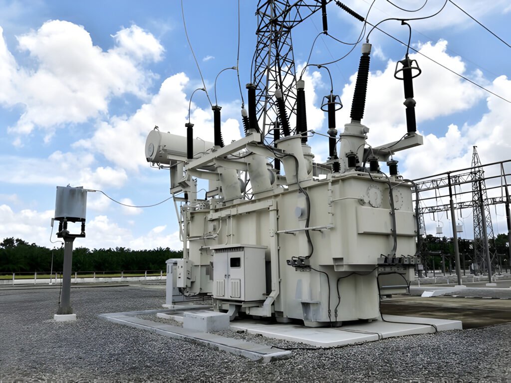
Power transformers are large-scale electrical devices used in power transmission and distribution systems. They are designed to handle high voltage and power levels, typically ranging from 500 kVA to 1000 MVA and voltages above 33 kV. Power transformers are critical components in electrical grids, enabling the efficient transfer of power over long distances.
The primary function of a power transformer is to step up the voltage generated at power plants to high levels suitable for long-distance transmission, and then step down the voltage at substations for distribution to end-users. This voltage transformation minimizes power losses and ensures economical power transmission.
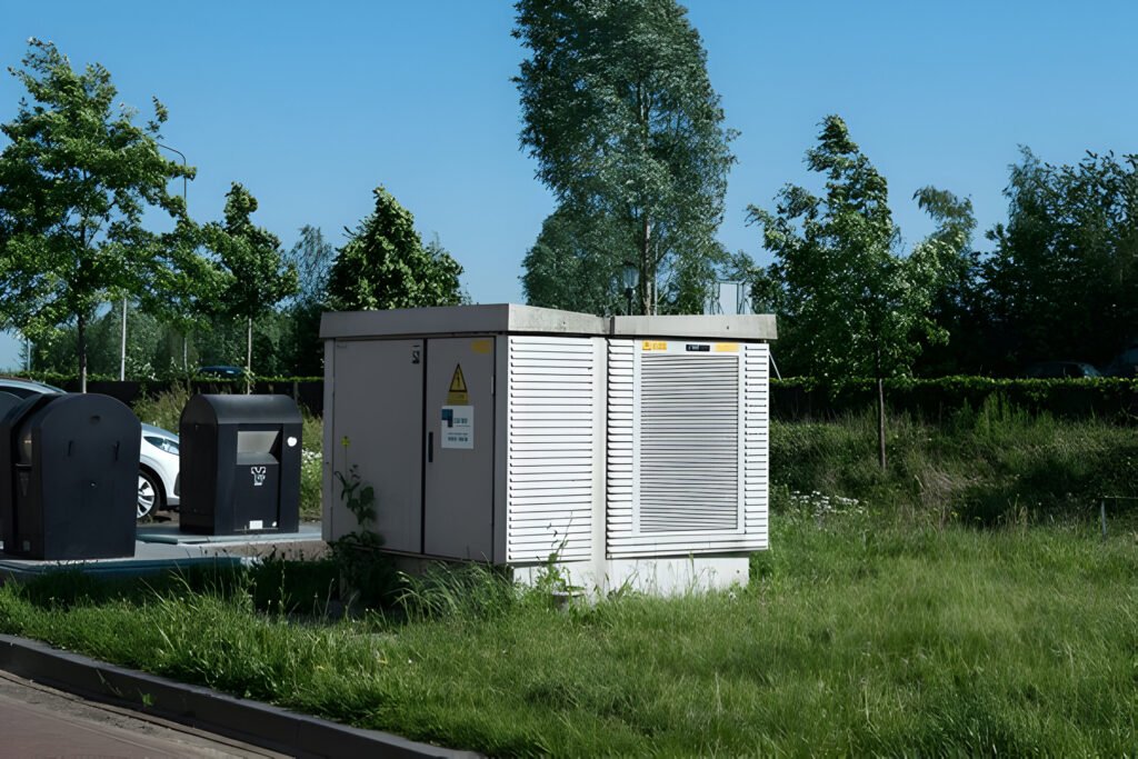
Distribution transformers are the final step in the power delivery system, transforming voltage from the primary distribution level to the secondary distribution level or the utilization level. They are typically rated between 5 kVA and 500 kVA and operate at voltages ranging from 11 kV to 33 kV on the primary side and 415 V or 240 V on the secondary side.
The main purpose of distribution transformers is to provide the appropriate voltage level for end-users, such as homes, businesses, and industrial facilities. They are commonly seen mounted on utility poles or placed in pad-mounted enclosures in residential and commercial areas.
Current transformers (CTs) are specialized instrument transformers designed to accurately measure alternating current (AC) in electrical power systems. They reduce high primary currents to manageable secondary levels while maintaining a precise current ratio between the primary and secondary windings. This ratio is determined by the number of turns in each winding.
CTs consist of a primary winding, secondary winding, and a magnetic core. The primary winding is connected in series with the conductor carrying the current to be measured, while the secondary winding is connected to the measuring instruments or protective devices. The magnetic core concentrates the magnetic flux produced by the primary current, inducing a proportional current in the secondary winding.
The secondary current is typically standardized at 1A or 5A, regardless of the primary current magnitude. This allows the use of standard measuring instruments and protective devices. The secondary winding is wound with many turns of fine wire to achieve the desired current ratio and provide isolation between the primary and secondary circuits.
Potential transformers (PTs), also known as voltage transformers (VTs), are instrument transformers designed to measure voltage in high-voltage electrical systems. They step down the high voltage to a safe, measurable level for monitoring and protection purposes. PTs provide a proportional voltage output that accurately represents the primary voltage while isolating the measuring instruments from the high-voltage circuit.
PTs consist of a primary winding connected in parallel with the high-voltage line and a secondary winding that supplies the reduced voltage to the measuring or protective devices. The primary winding typically has a large number of turns to handle the high voltage, while the secondary winding has fewer turns to produce a lower voltage. The turns ratio between the primary and secondary windings determines the voltage transformation ratio.
Audio transformers are specialized electrical components designed to optimize signal transfer and impedance matching in audio amplifiers and other sound equipment. They are constructed using two or more coils of wire wound around a common core, allowing for the efficient transfer of electrical energy from one circuit to another.
The primary function of an audio transformer is to convert the high-impedance output of an amplifier into a low-impedance signal suitable for driving speakers or other low-impedance loads. This impedance matching ensures maximum power transfer and minimizes signal loss, resulting in improved sound quality and efficiency.
RF transformers are specialized components designed to transfer high-frequency signals between different stages of a radio frequency (RF) circuit. These air-core transformers consist of two or more coils wound on a non-conductive core, typically made of ceramic or plastic. The primary coil receives the input signal, while the secondary coil delivers the output signal to the next stage of the circuit.
One of the primary functions of RF transformers is impedance matching. Impedance matching ensures that the maximum power transfer occurs between the source and the load, minimizing signal reflections and losses. By selecting the appropriate turns ratio between the primary and secondary coils, RF transformers can match the impedance of the source to the impedance of the load, optimizing signal transfer efficiency.
IF transformers, short for intermediate frequency transformers, are specialized components used in radio frequency (RF) circuits. They operate at the intermediate frequency stage of a superheterodyne receiver, which is typically between 455 kHz and 10.7 MHz. The primary function of an IF transformer is to couple the signal from one stage to another while providing selectivity and gain.
IF transformers consist of two or more tuned circuits that are inductively coupled. Each tuned circuit comprises an inductor and a capacitor, forming a resonant circuit tuned to the desired intermediate frequency. The coupling between the tuned circuits determines the bandwidth and selectivity of the transformer. Tighter coupling results in wider bandwidth, while looser coupling provides higher selectivity.
Dry-type transformers utilize air as the cooling medium, eliminating the need for oil or other liquid coolants. These transformers are categorized based on the insulation type, with cast resin and vacuum pressure impregnated being common options. Dry-type transformers find applications in various industrial facilities and commercial settings where safety and environmental concerns are critical factors. The absence of liquid coolants minimizes the risk of leaks and fires, making them a preferred choice in such environments.
The insulation materials used in dry-type transformers play a crucial role in their performance and durability. Cast resin transformers employ a solid insulating material, typically epoxy resin, which encapsulates the windings and provides excellent mechanical and thermal protection. This insulation offers high resistance to moisture, dust, and other environmental factors, ensuring reliable operation in demanding conditions. On the other hand, vacuum pressure impregnated transformers use a special varnish or resin to impregnate the windings, creating a solid insulation layer. This process enhances the transformer’s ability to withstand electrical stresses and improves its overall durability.
Oil-type transformers, also known as oil-filled, oil-immersed, or liquid-filled transformers, use liquid coolants for heat dissipation and insulation. These transformers offer superior cooling and insulation capabilities compared to dry-type transformers, making them more efficient in managing heat generated during operation.
The liquid coolant in oil-type transformers serves two primary functions: it absorbs and transfers heat away from the transformer’s core and windings, and it acts as an insulating medium to prevent electrical discharge. The most commonly used coolant is mineral oil, which has excellent dielectric properties and thermal stability.
Single-phase transformers are designed to operate with a single-phase AC power supply. They consist of a primary winding and a secondary winding wound around a common magnetic core. The primary winding receives the input voltage, while the secondary winding delivers the transformed output voltage. Single-phase transformers are commonly used in low-power applications, such as household appliances, lighting systems, and small electronic devices.
The power rating of single-phase transformers typically ranges from a few volt-amperes (VA) to several kilovolt-amperes (kVA). They are available in various voltage ratings and can be step-up, step-down, or isolation transformers. Single-phase transformers are relatively simple in construction and less expensive compared to three-phase transformers. However, they are not suitable for high-power applications due to their limited power handling capacity.
Three-phase transformers are used in power systems where three-phase AC power is required. They consist of three sets of primary and secondary windings, one for each phase, wound around a common magnetic core. The windings are arranged in a specific configuration, such as delta or wye (star), depending on the desired voltage and current relationships between the input and output.
Three-phase transformers are employed in high-power applications, such as power generation, transmission, and distribution systems. They are capable of handling large amounts of power, ranging from several hundred kVA to hundreds of MVA (megavolt-amperes). The three-phase design allows for efficient power transfer and balanced load distribution across the three phases.
Compared to using three single-phase transformers, a single three-phase transformer offers several advantages. It is more compact, cost-effective, and efficient. The balanced three-phase power supply minimizes voltage fluctuations and provides a stable power output. Three-phase transformers are also used in industrial settings, such as motor drives, heavy machinery, and large-scale electrical equipment.

Autotransformers are a unique type of transformer that features a single winding, which serves as both the primary and secondary. This winding has multiple taps at different points, allowing for variable voltage ratios. Autotransformers are more compact and economical compared to conventional two-winding transformers, as they require less copper and core material for construction.
Autotransformers find applications in voltage regulation, motor starting, and power distribution systems. They efficiently step up or step down voltages within a limited range, typically up to a 3:1 ratio. However, autotransformers do not provide electrical isolation between the input and output circuits, which is a key disadvantage compared to standard transformers.
Pulse transformers are specialized transformers designed to transmit rectangular electrical pulses with fast rise and fall times. They feature a compact design with low leakage inductance and high coupling between the windings. The core material is carefully selected to minimize losses and maintain pulse shape integrity.
Pulse transformers are extensively used in digital electronics, telecommunications, and radar systems. They play a crucial role in transmitting timing pulses, triggering thyristors or IGBTs, and providing galvanic isolation between circuits. Pulse transformers are also used in switch-mode power supplies (SMPS) to drive power switches and provide isolation between the input and output stages.
Military transformers are ruggedized transformers designed to withstand harsh environmental conditions and meet stringent military specifications. They are built to operate reliably in extreme temperatures, shock, vibration, and altitude conditions. Military transformers undergo rigorous testing to ensure their performance and durability in critical applications.
These transformers are used in various military systems, including radar, communication equipment, avionics, and power supplies. They are designed with high-quality materials, such as vacuum-impregnated windings, hermetically sealed enclosures, and special alloys for the core. Military transformers often incorporate additional features like electromagnetic shielding, transient suppression, and built-in protection devices to enhance their reliability and survivability in hostile environments.

When comparing open and closed delta configurations, learn which system delivers optimal power capacity and reliability for your electrical needs.
Read More
Power transformers step up voltage for transmission; distribution transformers step down voltage for end-users. Key differences in function and capacity.
Read More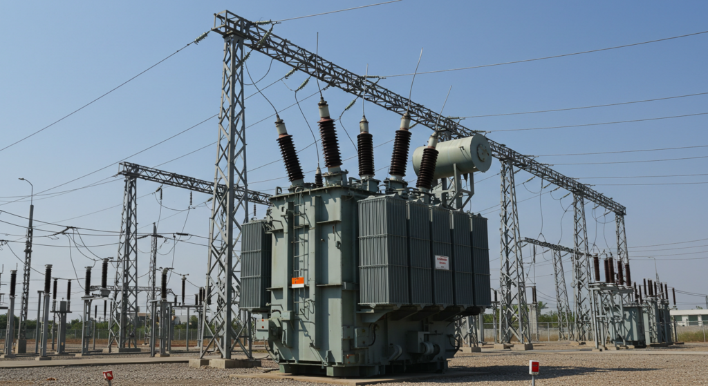
Oil-immersed transformers are a type of electrical transformer that uses oil for cooling and insulation.
Read More


