Transformers
What Is the Difference Between a Bushing and an Insulator
Bushings and insulators both insulate electrical components, but bushings also provide mechanical support.
Read More
Transformers are crucial components in electrical power systems, and their reliable operation is essential for ensuring a stable and uninterrupted power supply. To safeguard transformers from various electrical and mechanical faults, a range of protection systems are employed. These protection systems can be broadly categorized into two main types: electrical protection systems and mechanical protection systems.
In this article, we will delve into the details of each type of transformer protection system and their respective sub-categories.
Electrical protection systems are designed to detect and respond to electrical faults that may occur within the transformer or in the connected power system. These faults can include short circuits, overloads, and earth faults. The primary objective of electrical protection systems is to quickly isolate the faulty transformer from the rest of the power system to minimize damage and prevent the fault from propagating.
Differential protection is a highly sensitive and selective method of protecting transformers against internal faults. This protection system compares the currents entering and leaving the transformer at each winding. Under normal operating conditions, the currents entering and leaving the transformer should be equal, according to Kirchhoff’s Current Law. However, if a fault occurs within the transformer, the currents will differ, indicating the presence of a fault.
The differential protection system consists of current transformers (CTs) installed on each side of the transformer windings. These CTs measure the currents and send the signals to a differential relay. The relay compares the currents and calculates the difference between them. If the difference exceeds a predetermined threshold, the relay initiates a trip signal to the circuit breaker, disconnecting the transformer from the power system.
Overcurrent protection is designed to safeguard transformers against excessive currents that may result from overloads or external short circuits. Overloads occur when the transformer is subjected to currents beyond its rated capacity for an extended period. Short circuits, on the other hand, are sudden and severe faults that can cause extremely high currents to flow through the transformer.
Overcurrent protection systems utilize overcurrent relays, which monitor the current flowing through the transformer. These relays are set to operate at a specific current threshold and time delay. If the current exceeds the predetermined threshold for a certain duration, the relay sends a trip signal to the circuit breaker, disconnecting the transformer from the power system.
There are two main types of overcurrent protection: instantaneous overcurrent protection and time-delayed overcurrent protection. Instantaneous overcurrent protection responds immediately to high-magnitude fault currents, providing fast protection against severe short circuits. Time-delayed overcurrent protection, on the other hand, allows for a certain time delay before tripping, allowing for temporary overloads and coordination with other protective devices in the system.
Earth fault protection, also known as ground fault protection, is used to detect and clear faults that occur between a transformer winding and the earth (ground). Earth faults can arise due to insulation breakdown, mechanical damage, or contamination in the transformer.
Earth fault protection systems employ earth fault relays, which measure the current flowing through the transformer’s neutral point to the earth. Under normal conditions, this current should be zero. However, if an earth fault occurs, a current will flow through the neutral point, triggering the earth fault relay.
The earth fault relay is set to operate at a specific current threshold and time delay. When the relay detects an earth fault current above the set threshold, it sends a trip signal to the circuit breaker, isolating the faulty transformer from the power system.
Backup protection systems serve as a secondary line of defense in case the primary protection systems fail to operate or if a fault occurs outside the protected zone of the transformer. Backup protection ensures that faults are cleared even if the main protection systems malfunction, preventing the fault from persisting and causing extensive damage.
Backup protection systems typically include overcurrent relays, distance relays, or directional relays. These relays are set with higher current thresholds and longer time delays compared to the primary protection systems. This coordination ensures that the backup protection operates only if the primary protection fails or if the fault is located beyond the transformer’s protected zone.
In addition to electrical protection systems, transformers also require mechanical protection systems to safeguard against physical faults and abnormalities. Mechanical protection systems monitor various parameters such as pressure, temperature, and oil level to detect and respond to mechanical issues within the transformer.
The Buchholz relay is a mechanical protection device commonly used in oil-immersed transformers. It is installed in the connecting pipe between the transformer tank and the conservator tank. The Buchholz relay is designed to detect faults that occur within the transformer and generate gases or cause oil surges.
When a fault occurs inside the transformer, such as insulation breakdown or overheating, gases are generated and accumulate in the oil. These gases, being lighter than oil, rise and collect in the Buchholz relay. As the gas accumulates, it displaces the oil level in the relay, causing a float switch to operate. The float switch can be set to trigger an alarm or initiate a trip signal to the circuit breaker, depending on the severity of the fault.
In addition to gas accumulation, the Buchholz relay also detects oil surges caused by internal faults. When a severe fault occurs, such as a short circuit, the sudden release of energy causes the oil to surge towards the conservator tank. This oil surge passes through the Buchholz relay, activating a second float switch or a mercury switch, which initiates a trip signal to the circuit breaker.
Thermal protection systems are designed to monitor the temperature of the transformer and protect it from overheating. Overheating can occur due to various reasons, such as overloading, insufficient cooling, or high ambient temperatures. Prolonged overheating can deteriorate the transformer’s insulation, leading to premature aging and failure.
Thermal protection systems utilize temperature sensors, such as resistance temperature detectors (RTDs) or thermocouples, installed at critical locations within the transformer. These sensors continuously measure the temperature of the transformer windings, core, and oil.
The temperature signals from the sensors are sent to a temperature monitoring relay or a digital temperature controller. The relay or controller compares the measured temperature with predefined temperature thresholds. If the temperature exceeds the set limits, the relay initiates appropriate actions, such as triggering an alarm, activating cooling systems, or tripping the transformer offline.
Surge protection systems are designed to protect transformers from voltage surges and transient overvoltages. Voltage surges can occur due to lightning strikes, switching operations, or fault conditions in the power system. These surges can cause insulation breakdown, winding damage, and premature failure of the transformer.
Surge protection devices, such as surge arresters or metal oxide varistors (MOVs), are installed on the transformer’s terminals or in the substation. These devices limit the magnitude and duration of the voltage surges, diverting the excess energy to the ground.
Surge arresters are connected in parallel with the transformer windings and are designed to conduct when the voltage exceeds a certain threshold. They provide a low-impedance path for the surge current to flow to the ground, protecting the transformer from overvoltages.
MOVs are non-linear resistors that exhibit a decrease in resistance with increasing voltage. They are connected in parallel with the transformer and act as a voltage-dependent switch. When the voltage across the MOV exceeds a specific value, it starts conducting, limiting the voltage and protecting the transformer.
Pressure relief devices are mechanical protection systems that protect transformers from excessive pressure buildup inside the tank. Abnormal conditions, such as internal faults or severe overloading, can generate gases and cause a rapid increase in pressure within the transformer.
Pressure relief devices, such as pressure relief valves or explosion vents, are installed on the transformer tank. These devices are designed to open and release the excess pressure when it reaches a predetermined threshold. By relieving the pressure, they prevent the transformer tank from rupturing or exploding, which could cause significant damage and pose safety hazards.
Pressure relief valves are spring-loaded devices that automatically open when the internal pressure exceeds the set value. They allow the gases to escape from the transformer tank, reducing the pressure to a safe level. Once the pressure normalizes, the valve closes, preventing the ingress of moisture or contaminants.
Explosion vents, also known as rupture discs, are thin metal discs designed to rupture at a specific pressure. When the pressure inside the transformer reaches the rupture point, the disc bursts open, providing a rapid release path for the gases. Explosion vents are typically used in transformers with a high risk of severe internal faults.

Bushings and insulators both insulate electrical components, but bushings also provide mechanical support.
Read More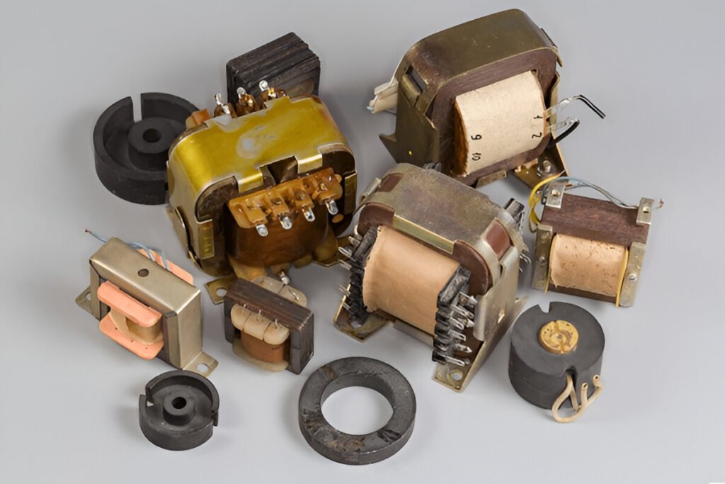
Discover the key differences between air core and ferrite core inductors, including their properties and applications.
Read More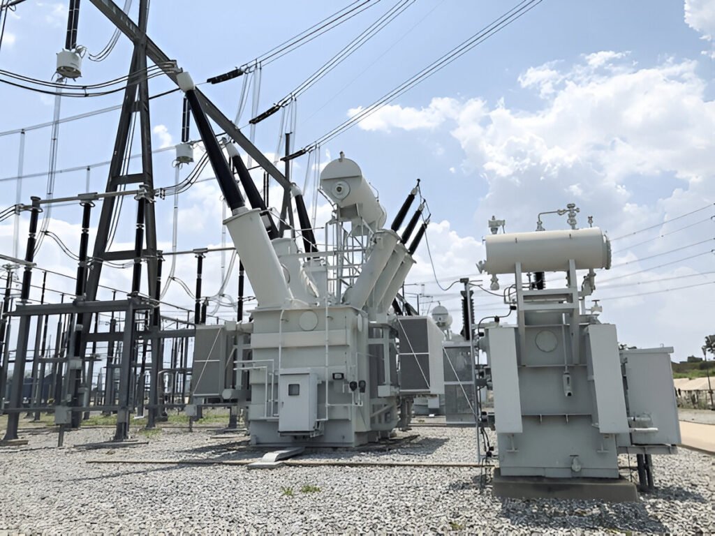
Learn how to calculate power losses in distribution transformers due to load and no-load factors.
Read More


