Transformers
How Does a CSP Transformer Work
Learn how CSP transformers convert solar energy to electricity through photovoltaic cells in this quick overview.
Read More
Three-phase motors, the workhorses of industrial applications, come in two main wiring configurations: wye (Y) and delta (δ). Identifying whether a motor is wired in wye or delta configuration is critical for proper installation, troubleshooting, and maintenance.
In this blog post, we will explore the differences between wye and delta configurations, focusing on their wiring arrangements and characteristics. We will also discuss various methods to determine a motor’s configuration, including examining nameplate information, analyzing terminal connections, performing voltage tests, and visually inspecting the windings.
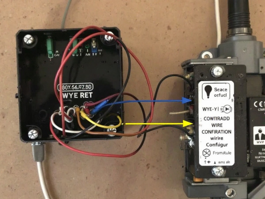
In a wye (Y) connected three-phase motor, the windings are connected at one common point, forming a “Y” shape. The common point is called the neutral or star point. Each winding has one end connected to this neutral point, while the other end is connected to one of the three phase terminals (U, V, or W).
The voltage across each winding in a wye-connected motor is equal to the phase voltage, which is the line voltage divided by √3. For example, if the line voltage is 480V, the phase voltage would be 277V (480V ÷ √3). The current in each winding is equal to the line current.
Wye-connected motors are suitable for applications that require high starting torque and efficiency. They are commonly used in high-voltage applications, as the voltage across each winding is reduced compared to the line voltage.
In a delta (δ) connected three-phase motor, the windings are connected in a triangular configuration. Each winding is connected between two phase terminals, forming a closed loop. The three windings are connected to the three phase terminals (U, V, and W) without a common neutral point.
In a delta-connected motor, the voltage across each winding is equal to the line voltage. However, the current in each winding is equal to the line current divided by √3. For example, if the line current is 10A, the current in each winding would be 5.8A (10A ÷ √3).
Delta-connected motors are suitable for applications that require high starting current and torque. They are commonly used in low-voltage applications, as the voltage across each winding is equal to the line voltage, allowing for higher power output.
The motor’s nameplate often provides the most straightforward way to identify the wiring configuration. Look for the following information:
If the nameplate is missing or illegible, other methods must be used to determine the configuration.
Analyzing the connections at the motor’s terminal box can reveal the wiring configuration:
In some cases, motors may have six terminals, allowing for both wye and delta connections. Consult the manufacturer’s documentation for specific wiring instructions.
Measuring the voltage between the motor’s terminals can help identify the configuration:
Always exercise caution when working with electrical systems, and follow proper safety protocols.
In some cases, visual inspection of the motor’s windings can help determine the configuration:
This method requires a good understanding of motor winding layouts and should be performed by qualified personnel.
Learn how CSP transformers convert solar energy to electricity through photovoltaic cells in this quick overview.
Read More
Compare transformer rectifiers and inverters to discover their unique roles in power conversion and why each matters for electrical systems.
Read More
Learn the steps to safely test a transformer and ensure it is functioning properly in this concise guide.
Read More


