Transformers
A Comprehensive Guide to Transformer Impedance
Dive into the fundamentals of transformer impedance and master its calculation and application in electrical systems.
Read More
Autotransformer and transformer have distinct differences in their symbols used in circuit diagrams and their practical applications. Below, we will discuss these differences in detail.
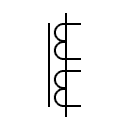
The autotransformer symbol is similar to that of an inductor but must include a tap, which indicates its variable transformation ratio. The tap is the key feature distinguishing autotransformers from inductors.
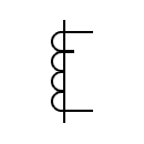
Transformers typically consist of two or more coils and transfer energy through electromagnetic induction. Transformer symbols vary based on their structure and purpose, such as iron-core or air-core transformers.
Symbols of Electrical Transformer
| Symbol | Description | Symbol | Description | |
|---|---|---|---|---|
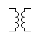
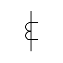
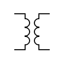 | Transformer Two windings and an air core Generic symbol | 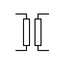 | Transformer Two windings and an air core | |
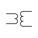
 | Transformer Two windings and an air core | 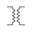 | Transformer Two windings and an air core | |
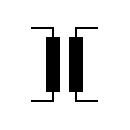
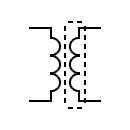
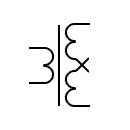
 | Transformer core Fe-Si Laminated core | 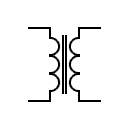 | Transformer with laminated core | |
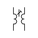
 | Shielded transformer | 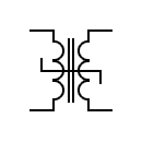 | Transformer with saturable reactor | |
 | Ferrite core transformer | 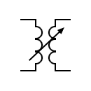 | Variable coupling transformer | |
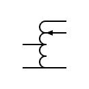
 | Voltage transformer | 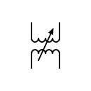 | Variable coupling transformer | |
 | Single-phase transformer with continuous current regulation | 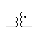 | Variable coupling transformer | |
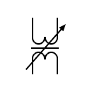
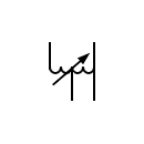
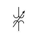 | Voltage transformer Transformer with voltage regulation | 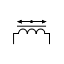 | Transformer with moving magnet | |
 | Adjustable transformer core | 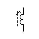 | Adjustable transformer core | |
 | Current transformer Pulse transformer | 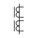 | Current transformer with two cores with a secondary winding on each core | |
 | Current transformer with dual core | 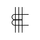 | Current transformer with three primary conductors | |
 | Current transformer with a secondary winding with a power | 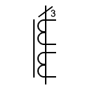 | Current transformer with two secondary windings on a single core and three primary | |
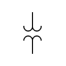
 | Current transformer with two secondary windings on a core | 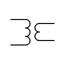 | Low-pass transformer | |
 | High-pass transformer | 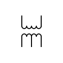 | Single-phase transformer with a shunt winding | |
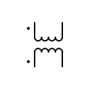 | Indicates the polarity of the windings | 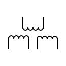 | Transformer with three windings | |
 | Transformer dual voltage |
Autotransformer Symbols
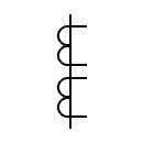
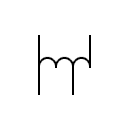 | Autotransformers | 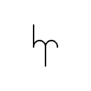 | Autotransformers | |
 | Variable autotransformer Single phase autotransformer with adjustable voltage | 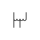 | Autotransformers | |
 | Variable autotransformer Single phase autotransformer with adjustable voltage | 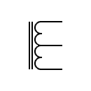 | Autotransformer with iron core |
Autotransformers are often used in applications where electrical isolation between the primary and secondary is not required, such as voltage adjustment and motor starting. They are also widely used in high-voltage power systems due to their low cost and high efficiency.
Autotransformer Application Examples
Transformers are primarily used in applications requiring voltage step-up or step-down and electrical isolation, such as power transmission and electronic device power supplies. Transformers provide electrical isolation between the primary and secondary, ensuring safety and reliability.
Transformer Application Examples
In summary, autotransformer and transformers have distinct differences in their symbols and practical applications. Autotransformers are suitable for applications without electrical isolation requirements, while transformers provide electrical isolation and are widely used in power transmission and electronic device power supplies. Understanding these differences allows engineers to choose the appropriate device for specific application needs.

Dive into the fundamentals of transformer impedance and master its calculation and application in electrical systems.
Read More
Distribution transformers are connected between high-voltage power lines and low-voltage secondary circuits to step down voltage for safe, efficient delivery.
Read More
Cast resin dry type transformers are safe, efficient, and eco-friendly power distribution solutions for indoor and outdoor applications.
Read More


